Question:
What is the functional and practical difference between Merge/Inheritance and internal/external Copy Geometry functionality?
Abe Headley, Penske Racing
Answered by: Gavin B. Rumble, PE
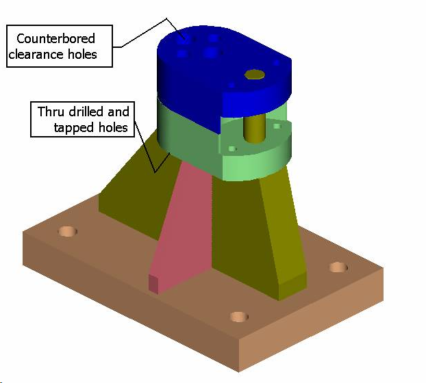
Frequently we run in to cases where we need two very similar (but not identical) parts in an assembly. In this case, one of the similar parts was a standalone part and had clearance holes, while the other was part of a weldment and had tapped holes (see below). Let’s stipulate that the top profile shape was specific and complex and needed to be identical.
 Since BOM issues precluded using a family table for both (the bottom piece is part of a weldment and the top has its own part number and drawing), this assembly was originally created using two separate unrelated parts. An as-built revision prompted us to seek a better way to eliminate the laborious feature redefine (twice…it wasn’t a very robust model and things started falling apart quickly).
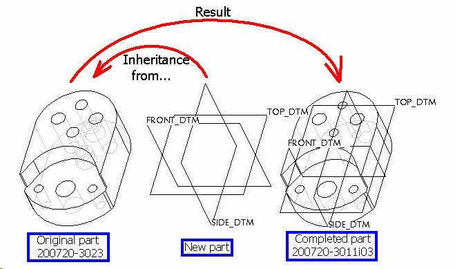
The answer was Inheritance…it works like this:

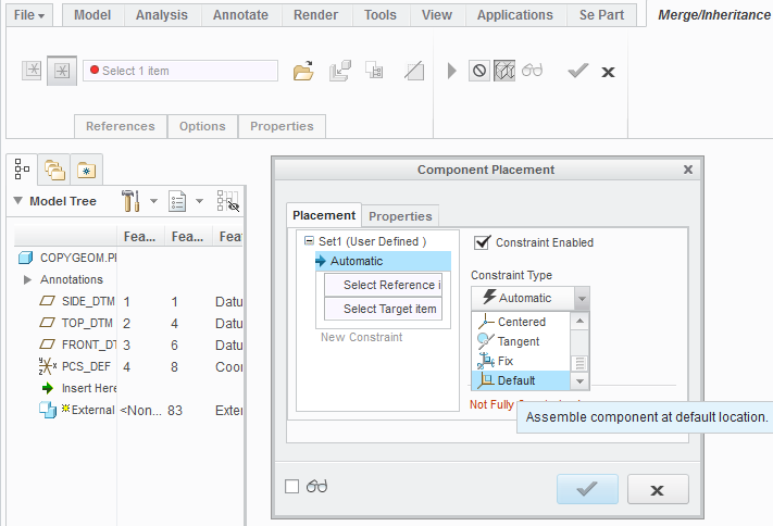
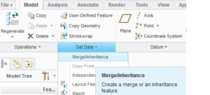
The result is a Solid model with Dependency and all the original parts features. Here are the menu pic’s. First, select Merge/Inheritance on the Get Data from the Model Tab.
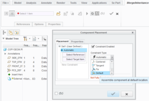
Then, place the Inheritance part into you current empty part…Default placement is generally best.
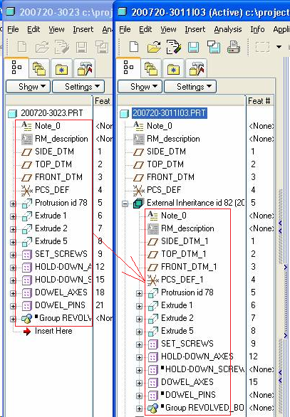
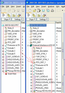
…and resulting Model Tree. Notice the duplicate section of the Model Tree in the new part.
The things to remember are:
1. If you select Dependent the resulting model is fully associative and there ARE NO ASSEMBLY REFERENCES to worry about.
2. You can modify (Edit) the features in the resulting SOLID model, but only if you define Variability in the Dims, Parameters, etc; however, you can quite easily continue modeling on the resulting part, creating additional features just like any other part.
3. All parameters come along, however they reside in the Inheritance Feature, not in the standard parameter table. You access them similar to Analysis Feature parameters by using relations to assign them to part parameters, but instead of using parameter_name:fid_id# you use parameter_name:iid_id#. In this case the material parameter would be made available to the part (and subsequently to the drawing) by creating the following relation.
/* Assign inheritance parameters to the new part parameters
MATERIAL = MATERIAL:iid_82
4. If you attempt to Show Dims in the drawing where the new part is displayed you will have trouble when you try to format the values (fractional or 2-place decimals, etc) because the system will force you to declare them as Variable Dims which you probably do not want to do. Use Created Dims instead.
5. If you later determine that one or more of the driving dimensions needs to be different in the resulting part, simply redefine the Inheritance Feature and declare that dimension to be Variable (Thickness_dim for example) and then give it the new value.
6. Not only are there no Assembly References, the source part need not be available (in your workspace or in session) going forward. You can redefine the Inheritance Feature locally if you like.
This procedure can also be used to make Mirror Image parts using surfaces from the first part which are mirrored and solidified in the second part.
Copy Geometry, while an extremely useful tool, cannot do most of these things. First, Copy Geometry can only bring in Surfaces, Edges/Curves, and Datums. Second, there is no resulting visibility of the source part’s features. Thirdly, no Parameters come along with the geometry. Finally, if you attempt to Redefine (Edit Definition) an External Copy Geom and do not retrieve the source part, you will be very limited in what you can actually do.
Hope this was helpful…leave comments or send me an email if you have questions. [GBR]
(4755)